Search This Blog

Showing posts with label photogrammetric surveying ppt. Show all posts

Wednesday, May 23, 2018

PHOTOGRAMMETRIC SURVEYING AND 3D MODELING USING UNMANNED AERIAL VEHICLE ( DRONES ) --- PART 4 ( UAV FLIGHT PLANNING)


FLIGHT PLANNING

For photogrammetric surveying and 3D modelling of the study area, the android applications Pix4d capture and drone deploy were capable of executing the flight plan. The flight planning was carried out based on different factors such as the overall area of the site to be covered, the precision level (spatial resolution), the overall flight time, and the speed limit, and the height of the buildings. The flying height and the flying view of a UAV totally depends upon 3 factors, the spatial resolution of the eventual images, the focal length of the camera and type of mission we are planning.


Flight plan requirements to carry out UAV based coverage over BIT Campus for 3-D modelling


       Pick a Time to Fly: one of the most important steps in using your drone to make a 3D model is to pick a good time to fly. Besides avoiding high winds or rain, it’s also important to pick a time with good lighting. The worst time of day? Too early or too late in the day because that’s when the shadows are longest and will have the greatest effect on the outcome of the model.

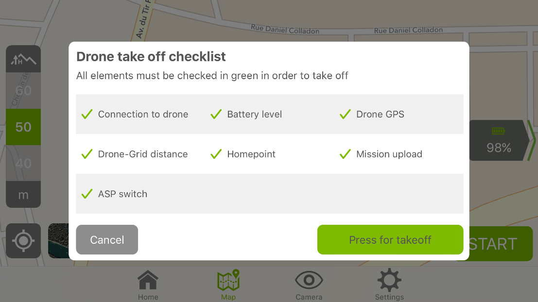
    Capture Nadir Imagery: Start by capturing nadir imagery, photos captured from directly above looking down, using the free Drone Deploy flight app (iOS or Android). He simply outlines the area he wants to fly on a base layer map, and the app generates a flight plan. Following a safety check, the drone automatically takes off, flies along the automated flight path capturing images and then lands.

Circle the Structure to Capture Oblique Imagery: if you’re making a 3D model of relatively flat terrain, an overhead flight might be sufficient to make a good model. However, if you’re modeling a structure or rock formation with steep, vertical or concave sides, overhead images don’t capture a good view of the sides of the structure. For this reason, Jeff recommends flying two additional orbital flights around the structure capturing oblique imagery to improve the quality of your model. When capturing oblique images it’s important to avoid capturing the horizon within your images. When Jeff makes these two orbital flights, he manually triggers the camera shutter to take each picture. However if you’re just starting out, you might experiment with flying very slowly and setting the camera through your drone’s flight app to automatically capture images every 3–5 seconds.


Process the Imagery to generate 3D Model: Upload all photos from all flights to Drone Deploy or any other software such as PhotoScan Agisoft or Pix4D capture and choose to process the imagery as a “structure.” After a few hours, Drone Deploys cloud-based processing stitched all the images together and the 3D model was complete.


 Fig: Camera position over study area

                           Technical issues and problem occurred during fly

Initially, while connecting the drone with the mobile app, connectivity problems were faced owing to version issues. This was due to not using the updated version of the mobile app interfacing the drone device. While using DJI Mavic Pro with Pix4D Capture version 2.9.0 running on iOS 11.1.2 on an iPhone 6, taken several attempts on double grid pattern for 3D modelling. The controller has twice indicated for "check app" and the app alerted that there is an error and it goes back into the landing mode.  In such case, one need to manually fly back to a safe landing point. Even after the successful pre-flight check sometimes the application encounter some technical problem during fly, this might be the internal issues of the application and need to be updated.

PHOTOGRAMMETRIC SURVEYING AND 3D MODELING USING UNMANNED AERIAL VEHICLE ( DRONES ) --- PART 3 ( UAV VOLUMETRIC ANALYSIS )


Volumetric analysis and Calculation for Accuracy check for UAV acquired Images

Volume measurement with is an extremely fast, accurate and cost-effective method to analyse volumes on our maps from any device. User tests have found that volume measurements with UAV acquired are accurate within 1-2% of traditional ground-based measurements.   PhotoScan calculates area of the surface as a  sum of areas for all the faces in the model, so if we have closed volume prior to calculation bottom area will be also calculated. Also note that side polygons will be also taken into account, so the result will be greater than area of 2D projection of the model to the XY plane.


Fig:selected area for volume calculation


Fig:selected area-close holes and calculated volume


Fig: sand on the ground (selected for volume calculation)

 
Fig:Part on the ground selected for volume calculation

Fig:  Actual view of the selected portion


Fig: volume calculation (close hole)

Negative value indicates than the surface normal are pointed inside the model as it is depth volume calculation. And it is a common situation for quarries or interior projects. The area selected was around 125.5 meter square and volume is 9.78 meter cube.


Monday, May 21, 2018

PHOTOGRAMMETRIC SURVEYING AND 3D MODELING USING UNMANNED AERIAL VEHICLE ( DRONES ) --- PART 2 ( UAV Photogrammetric Survey )

                                                       DRONEWORK


                             UAV Photogrammetric survey
Photogrammetric approaches are is in use for the last 150 years. During that time, the photogrammetry experienced substantial growths from analogue to today's digital techniques (Uysal et al., 2015).  Photogrammetry helps in determining the geometric properties of objects from images. The output of photogrammetry is typically a map, a drawing or a 3D model of some real-world object or land mass. It is the art of making maps and precise measurements from photographs, especially from aerial surveying. Digital images captured from UAV are frequently processed using conventional methods or using the new and efficient techniques with the specific software. The advantages of using UAVs for photogrammetric surveying are that their quickness, position, and stabilisation can be controlled correctly, so successive, distortion-free above ground images of a site can be acquired, which can then be processed to create 3D point clouds, digital terrain models, contour maps, digital surface model or can also be merged into a 2D or 3D orthomosaic image.
                                 
The fundamental principle used by photogrammetry is aerial Triangulation. In this technique, we acquire data from at least two dissimilar points.  The persistence of taking images from more than 2 points is to generate lines of sight. Once these lines of sight are arranged, we linked them to trace a point where they encounter and thus analyse the coordinates of the desired point (Castillo et al., 2017). The ability to speedily take aerial image from vertical, horizontal, and oblique angles allows a high degree of accuracy and flexibility which basically cannot be achieved by any traditional means, or by terrestrial surveying (http://libguides.wustl.edu/drones4data).

Agisoft PhotoScan, Pix 4d mapper and other existing software supports measuring distances between control points, as well as of surface area and volume of the reconstructed 3D model. All these measurement are generally performed on the generated 3D mesh. For distance measurement the existing softwares enables measurements of direct distances between the points of the reconstructed 3D scene. The points used for distance measurement must be defined by placing markers in the corresponding locations. Model coordinate system must be also initialized before the distance measurements is performed. Alternatively, the model can be scaled based on known distance (scale bar) information. For measuring distance in the study site, we placed multiple markers above the buildings and in the front lawn, created scale bar from 3D view context menu and finally viewed the distance in estimated value mode in the Agisoft PhotoScan. Distance between cameras are also measured in the workspace in the similar manner. Surface area and volume means, or by terrestrial surveying (http://libguides.wustl.edu/drones4data).


                                 Figure 1 : snapshot showing markers taken above building and in lawn


                    Table 1: Details of the marker
Labels
X/East
Y/North
Z/Altitude(m)
Point 1
85.441448
23.412947
588.20
Point 2
85.441446
23.412949
574.12
Point 3
85.441471
23.412950
587.40
Point 4
85.441529
23.412773
587.14
Point 5
85.441621
23.412796
587.02
Point 6
85.441555
23.412972
587.95
Point 7
85.441508
23.413190
573.79
Point 8
85.441702
23.413247
573.65
Point 9
85.441476
23.413224
574.16
Point 11
85.441329
23.413388
575.14
Point 12
85.441412
23.413404
575.64


Table 2:  Calculated distance

Labels


Distance(m)
 Point 1_Point 2
14.07
Point 7_Point 8
20.75
Point 4_Point 5
9.72


Agisoft PhotoScan, Pix 4d mapper and other existing software supports measuring distances between control points, as well as of surface area and volume of the reconstructed 3D model. All these measurement are generally performed on the generated 3D mesh. For distance measurement the existing softwares enables measurements of direct distances between the points of the reconstructed 3D scene. The points used for distance measurement must be defined by placing markers in the corresponding locations. Model coordinate system must be also initialized before the distance measurements is performed. Alternatively, the model can be scaled based on known distance (scale bar) information. For measuring distance in the study site, we placed multiple markers above the buildings and in the front lawn, created scale bar from 3D view context menu and finally viewed the distance in estimated value mode in the Agisoft PhotoScan. Distance between cameras are also measured in the workspace in the similar manner. Surface area and volume measurements of the reconstructed 3D model of the study area also performed after defining the scale and coordinate system of the scene. To measure surface area and volume, one has to use Measure Area and Volume command from the Tools menu. Surface area is measured in square meters, while mesh volume is measured in cubic meters. Volume measurement can be performed only for the models with closed geometry.


Watch  next part for more information .


Sunday, May 20, 2018

PHOTOGRAMMETRIC SURVEYING AND 3D MODELING USING UNMANNED AERIAL VEHICLE ( DRONES ) ----- PART 1

DRONEWORK

Photogrammetry, UAVs, Flight planning, DEM generation, Orthophoto, 3-D Modelling, UAV image classification , Illumination conditions for different scenes .


Unmanned Aerial Vehicle (UAV), generally known as a drone are nowadays a worthy source of data for 2D & 3D mapping, quick inspection & continuous monitoring, and for many other applications. Their ability in quick deployment, manoeuvre, and fast data collection at a very high spatial and temporal resolution is unprecedented. In this study we have attempted to understand the usability of UAV for planimetric and topographic mapping. We have tried to capture various man-made and natural objects using different viewing geometry, flight plans and in various acquisition modes. Initially, the captured images were aligned, and first level point clouds were created using photogrammetric techniques which depend upon camera position (using GPS and viewing geometry). These 1st-level points were densified at the 2nd level and then 3D-mesh were created. Finally, ortho-mosaic covering the region of capture was derived, and 3D-stereoscopic image of the study area was generated which helps in visualising the captured area interactively. Planimetric measurements (such as height, surface area) were carried out using markers on the 3D-tiled model. Volumetric analysis was also carried out on the 3D-solid mesh data using free-style selection. Overall 10 different results were generated: 3D-solid mesh, wireframe, textured model, tiled model, DEM, DSM, contour lines, stereoscopic view, ortho-mosaic and video using individual ortho-rectified images. We have utilise various existing softwares (in demo mode) such as Agisoft Photoscan, Pix4D Capture, Pix4D Mapper, and Drone Deploy for various purposes. We have validated the UAV derived measurements with the ground measurements and the error varied within few centimetres which is unimaginable (in terms of accuracy, cost and time efficiency) with the current existing satellite based or flight based technologies. Classification of the images were also carried out, Image classification refers to the task of extracting information classes from a multiband raster image. Both supervised and unsupervised classification were performed on the orthomosaic data of the UAV image. With the ArcGIS Spatial Analyst extension, there is a full suite of tools in the Multivariate toolset to perform supervised and unsupervised classification .The classification process is a multi-step workflow. Principal component analysis was also done on the data it has been used for visualization of complex data and developed to capture as much of the variation in data as possible. After the successful classification of the orthomosaic data the accuracy assessment of classified data were performed .In the context of information extraction by image analysis, accuracy “measures the agreement between a standard assumed to be correct and a classified image of unknown quality.Classification error occurs when a pixel (or feature) belonging to one category is assigned to another category. Errors of omission occur when a feature is left out of the category being evaluated; errors of commission occur when a feature is incorrectly included in the category being evaluated so that the project can be completed with more accuracy. 
    
                        
UAV is an unmanned-winged system, functioned remotely by a human operator or independently by an on-board system. UAV is also  defined as a "powered, aerial vehicle that does not carry a human operator, uses aerodynamic forces to provide vehicle lift, can fly autonomously or be piloted remotely, can be expendable or recoverable, and can carry a lethal or nonlethal payload" (http://TheFreeDictionary.com.).The term UAV is generally used in the branch of science that deals with the collection, analysis, and interpretation of data relating to the earth's surface. Based on their size, weight, endurance & range and flying altitude, it is also terms as Remotely Piloted Vehicle (RPV), Remotely Operated Aircraft (ROA), Remote Controlled (RC) Helicopter, Unmanned Vehicle Systems (UVS) etc.(Remondino et al., 2011). Currently existing satellites and manned vehicles are the main source of obtaining spatial data, but they are unable to collect data in real time, as well as they are too expensive. Therefore, we need a cheaper, more suitable and real-time approach to get spatial data. Compared with spaceborne remote sensing, UAV remote sensing has a feature of higher temporal resolution, and can also avoid the effect of cloud; relative to airborne remote sensing(Barazzetti et al., 2014).UAV based Remote Sensing is the new addition for significant mapping, real-time survey and monitoring activities for numerous applications. As compared to existing piloted aerial system, UAV is considerably cheaper to use, easy to handle and manoeuvre (Fraseret al., 2015). It can be used (take-offs and landings) even in inaccessible areas and has a low noise operation as compare to other devices. With the help of UAVs we can collect high spatial resolution, multi-perspective, multi sensor imagery over a study site(Fritz et al., 2017).A typical image-based field surveying with UAV systems require a flight or mission planning, GCPs measurement,image acquisition, camera calibration, image orientation and image processing for 3D information extraction (Grenzdörffer et al., 2011).


PHOTOGRAMMETRIC SURVEYING AND 3D MODELING USING UNMANNED AERIAL VEHICLE ( DRONES ) --- PART 5

STEPS OF DATA PROCESSING FOR ANY UAV BASED WORK   All acquired images from digital camera were downloaded into the computer after f...